旧版opengl-渲染立方体贴图布局,了解glTexCoord3f参数 [英] legacy opengl - rendering cube map layout, understanding glTexCoord3f parameters
问题描述
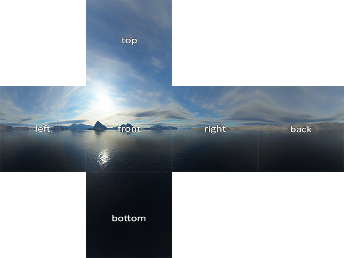
我想渲染一个立方体地图布局(正交投影)-类似于此.让我们专注于+ X脸(图片右侧).呈现+ X face的代码如下所示:
I would like to render a cube map layout (orthographic projection) - something like this. Let's focus on the +X face (right on the picture). The code which renders +X face looks this way:
glBegin(GL_QUADS);

glTexCoord3f(1, 1, -1);
glVertex2i(0,0);

glTexCoord3f(1, 1, 1);
glVertex2i(256,0);

glTexCoord3f(1, -1, 1);
glVertex2i(256, 256);

glTexCoord3f(1, -1, -1);
glVertex2i(0, 256);

glEnd();
glTexCoord3f似乎使用ndc值,但我不明白为什么y值对于前两个顶点为正,而对于下两个顶点为负,从我的理解来看,它应该是相反的(我想我从立方体中心).
It looks like that glTexCoord3f uses ndc values, but I don't understand why y value is positive for the first two vertices and negative for the next, from my understanding it should be opposite ( I imagine that I observe cube faces from the cube center).
推荐答案
没有glTexCoord3D不使用NDC !!! 而是它的方向矢量.
No glTexCoord3D does not use NDC !!! its a direction vector instead.
我过去一直在努力... ... GL_TEXTURE_CUBE_MAP很难从...开始.
I was struggling in the past with the same ... GL_TEXTURE_CUBE_MAP are hard to start with ...
为了使事情变得简单,这里是旧API(我的引擎的C ++成员)中的我的渲染器:
To make things easier here is mine render in old API (C++ member from mine engine) for those:
void OpenGL_TXR::cube_draw_CW(double size,int unit)
    {
    int i,j;
    double  a=size;
    double  pnt[8][3]=
        {
        +a,-a,+a,
        +a,+a,+a,
        -a,+a,+a,
        -a,-a,+a,
        +a,-a,-a,
        +a,+a,-a,
        -a,+a,-a,
        -a,-a,-a
        };
    int     tab[24]=
        {
        0,1,2,3,
        7,6,5,4,
        4,5,1,0,
        5,6,2,1,
        6,7,3,2,
        7,4,0,3
        };
    glColor3f(1,1,1);
    glBegin(GL_QUADS);
    for (i=23;i>=0;i--)
        {
        j=tab[i];
        glMultiTexCoord3dv(GL_TEXTURE0+unit,pnt[j]);
        glVertex3dv(pnt[j]);
        }
    glEnd();
    }
size是多维数据集的一半大小,而unit是纹理单位,绑定了多维数据集贴图.
但是,它渲染了一个带纹理的立方体.如果要渲染布局,则只需使用不同的顶点,但使用相同的纹理坐标即可.像这样:
size is the cube half size and unit is texture unit where is your cube map binded.
But it renders a textured cube. If you want to render your layout then just use different vertexes but the same texture coords. Something like this:
void cube_draw2D_CW(double size,int unit)
    {
    int i,j;
    //   U
    // W N E S
    //   D
    const double a=size,a0=-3.0*a,a1=a0+a+a,a2=a1+a+a,a3=a2+a+a;
    const double b=1.7320508075688772935274463415059; // sqrt(3.0)
    double  pnttxr[8][3]=
        {
        +b,-b,+b,
        +b,+b,+b,
        -b,+b,+b,
        -b,-b,+b,
        +b,-b,-b,
        +b,+b,-b,
        -b,+b,-b,
        -b,-b,-b
        };
    double  pntver[24][3]=
        {
        a1+a,a0+a-a,+0.0,
        a1+a,a0+a+a,+0.0,
        a1-a,a0+a+a,+0.0,
        a1-a,a0+a-a,+0.0,

        a1+a,a2+a-a,+0.0,
        a1+a,a2+a+a,+0.0,
        a1-a,a2+a+a,+0.0,
        a1-a,a2+a-a,+0.0,

        a0+a,a1+a-a,+0.0,
        a0+a,a1+a+a,+0.0,
        a0-a,a1+a+a,+0.0,
        a0-a,a1+a-a,+0.0,

        a1+a,a1+a-a,+0.0,
        a1+a,a1+a+a,+0.0,
        a1-a,a1+a+a,+0.0,
        a1-a,a1+a-a,+0.0,

        a2+a,a1+a-a,+0.0,
        a2+a,a1+a+a,+0.0,
        a2-a,a1+a+a,+0.0,
        a2-a,a1+a-a,+0.0,

        a3+a,a1+a-a,+0.0,
        a3+a,a1+a+a,+0.0,
        a3-a,a1+a+a,+0.0,
        a3-a,a1+a-a,+0.0,
        };
    int     tabtxr[24]=
        {
        4,0,3,7,    // D
        1,5,6,2,    // U
        3,2,6,7,    // W
        0,1,2,3,    // N
        4,5,1,0,    // E
        7,6,5,4,    // S
        };
    int     tabver[24]=
        {
        0,1,2,3,
        4,5,6,7,
        8,9,10,11,
        12,13,14,15,
        16,17,18,19,
        20,21,22,23,
        };
    glColor3f(1,1,1);
    glBegin(GL_QUADS);
    for (i=23;i>=0;i--)
        {
        j=tabtxr[i];
        glMultiTexCoord3dv(GL_TEXTURE0+unit,pnttxr[j]);
        j=tabver[i];
        glVertex3dv(pntver[j]);
        }
    glEnd();
    }
这里预览:
这篇关于旧版opengl-渲染立方体贴图布局,了解glTexCoord3f参数的文章就介绍到这了,希望我们推荐的答案对大家有所帮助,也希望大家多多支持IT屋!
