用于Graphviz / PyGraphviz中有向图的NetworkX样式弹簧模型布局 [英] NetworkX-style spring model layout for directed graphs in Graphviz / PyGraphviz
问题描述
spring_layout 函数),而PyGraphviz有几种弹簧布局算法(可通过 neato 程序和其他函数访问),这些算法将有向图布置成无向图。真正处理图中方向的唯一Graphviz / PyGraphviz布局程序是 dot ,但是 dot 创建分层布局,而不是
下面是一个示例,显示了NetworkX和PyGraphviz之间针对有向图的弹簧布局的区别:
import networkx as nx
import pygraphviz as pgv
import matplotlib.pyplot as ppt
edgelist = [(1,2 ),(1,9),(3,2),(3,9),(4,5),(4,6),(4,9),(5,9),(7,8), (7,9)]
nxd = nx.DiGraph()
nxu = nx.Graph()
gvd = pgv.AGraph(定向=真)
gvu = pgv.AGraph()
nxd.add_edges_from(edgelist)
nxu.add_edges_from(edgelist)
gvd.add_edges_from(edgelist)
gvu.add_edges_from(edgelist )
pos1 = nx.spring_layout(nxd)
nx.draw_networkx(nxd,pos1)
ppt.savefig('1_networkx_directed.png')
ppt.clf ()
pos2 = nx.spring_layout(nxu)
nx.draw_networkx(nxu,pos2)
ppt.savefig( '2_networkx_undirected.png')
ppt.clf()
gvd.layout(prog ='neato')
gvd.draw('3_pygraphviz_directed.png')
gvu.layout(prog ='neato')
gvu.draw('4_pygraphviz_undirected.png')
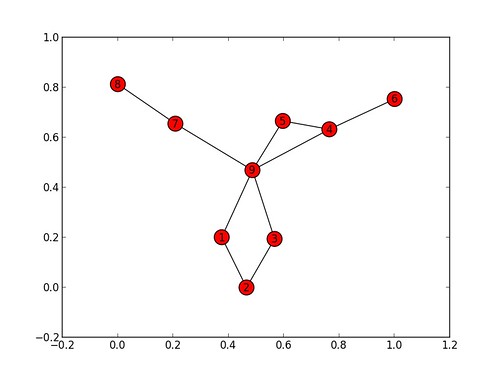
1_networkx_directed.png :( http://farm9.staticflickr.com/ 8516 / 8521343506_0c5d62e013.jpg )
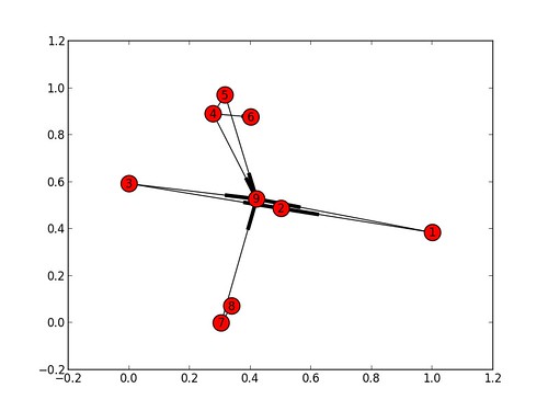
2_networkx_undirected.png:( http://farm9.staticflickr.com/8246/8521343490_06ba1ec8e7.jpg )
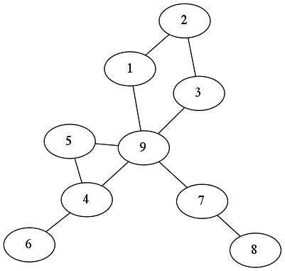
3_pygraphviz_directed.png:( http://farm9.staticflickr.com/8365/8520231171_ef7784d983.jpg )
4_pygraphviz_undirected.png :( http://farm9.staticflickr.com /八百五十二分之八千○九十三0231231_80c7eab443.jpg )
第三和第四个数字基本相同,但对于箭头(整个数字已经旋转,但除此之外,还有没有不同)。但是,第一个和第二个数字的布局是不同的 - 不仅仅是因为NetworkX的布局算法引入了随机性元素。
重复运行上面的代码表明,这不是偶然发生。 NetworkX的 spring_layout 函数显然是在这样的假设下编写的:如果从一个节点到另一个节点存在弧线,则第二个节点应该比第一个节点更靠近图形中心即如果 edgelist 中描述的图是有向的,则节点2应该比节点1和3更靠近节点9,节点6应该比节点4更靠近节点9是,并且节点8应该比节点7更接近节点9;这并不总是如我们在上面的第一幅图中从节点4和5看到的那样完美地工作,但是与使得2和9都接近相比,这是一个小问题从我的角度来看,中心和'错误'非常轻微)。换句话说,NetworkX的 spring_layout 既是分层的,也是强制的。
这是一个很好的功能,因为它使得核心/外围结构在有向图中更加明显(其中,根据您使用的假设,即使有大量输出弧,没有输入弧的节点也可以被认为是外围的一部分)。 @skyebend在下面解释了为什么大多数布局算法将有向图看作是无向的,但上面的图显示(a)NetworkX对待它们的方式不同,以及(b)它以有利于分析的原则方式进行操作。
这可以使用PyGraphviz / Graphviz复制吗?
不幸的是,文档和评论源代码 NetworkX的 spring_layout (实际上 fruchterman_reingold_layout )函数没有提供线索为什么NetworkX产生它的结果。
这是使用PyGraphviz的结果使用NetworkX spring_layout 函数绘制网络(请参阅我对此问题的回答OW)。
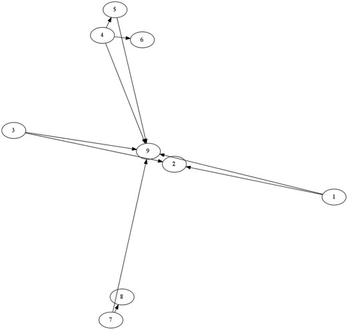
5_pygraphviz_plus_networkx.png:
( http://farm9.staticflickr.com/ 8378 / 8520231183_e7dfe21ab4.jpg )
解决方案好的,我想我知道了,所以我要回答我自己的问题。我不认为它可以在PyGraphviz本身中完成。但是,可以指示PyGraphviz从NetworkX获取节点位置,但将它们绑定(使用!),以使 neato 除了橡皮戳由 spring_layout 计算的节点位置外,程序不能实际执行任何操作。将以下代码行添加到上面:
for k,v in pos1.iteritems():
gvd格式(v [0] * 10,v [1] * 10)
gvd.layout(' prog ='neato')
gvd.draw('5_pygraphviz_plus_networkx.png')
结果并不完美 - 为了阻止节点彼此重叠,我必须将坐标乘以10,这显然是一种混乱 - 但这是一种改进,即节点0 (在NetworkX中进行布局的好处),并且有适当的箭头不会被节点自己吞噬(利用PyGraphviz进行绘图)。
我意识到,这不是我所要求的,尽管(即使用PyGraphviz / Graphviz本身的解决方案)。
如果有人能提供更好的解决方案,我会很高兴的!
编辑:没有人提供了更好的解决方案到上面阐述的问题,所以我要接受我自己的答案来表明它实际上有效。然而,我也投票skyebend的答案,因为 - 虽然它不能解决问题 - 这对理解潜在问题非常有用。
NetworkX is mostly for graph analysis, PyGraphviz mostly for drawing, and they're designed to work together. However, there's at least one respect in which NetworkX's graph drawing (via MatPlotLib) is superior to PyGraphviz's graph drawing (via Graphviz), namely that NetworkX has a spring layout algorithm (accessible via the spring_layout function) specifically for directed graphs while PyGraphviz has several spring layout algorithms (accessible via the neato program, and others) that lay out directed graphs as if they were undirected graphs. The only Graphviz / PyGraphviz layout program that really handles direction in a graph is dot, but dot creates hierarchical layouts, not force-directed layouts.
Here is an example that shows the difference between NetworkX and PyGraphviz for spring layouts of directed graphs:
import networkx as nx
import pygraphviz as pgv
import matplotlib.pyplot as ppt
edgelist = [(1,2),(1,9),(3,2),(3,9),(4,5),(4,6),(4,9),(5,9),(7,8),(7,9)]
nxd = nx.DiGraph()
nxu = nx.Graph()
gvd = pgv.AGraph(directed=True)
gvu = pgv.AGraph()
nxd.add_edges_from(edgelist)
nxu.add_edges_from(edgelist)
gvd.add_edges_from(edgelist)
gvu.add_edges_from(edgelist)
pos1 = nx.spring_layout(nxd)
nx.draw_networkx(nxd,pos1)
ppt.savefig('1_networkx_directed.png')
ppt.clf()
pos2 = nx.spring_layout(nxu)
nx.draw_networkx(nxu,pos2)
ppt.savefig('2_networkx_undirected.png')
ppt.clf()
gvd.layout(prog='neato')
gvd.draw('3_pygraphviz_directed.png')
gvu.layout(prog='neato')
gvu.draw('4_pygraphviz_undirected.png')
1_networkx_directed.png:(http://farm9.staticflickr.com/8516/8521343506_0c5d62e013.jpg)
2_networkx_undirected.png:(http://farm9.staticflickr.com/8246/8521343490_06ba1ec8e7.jpg)
3_pygraphviz_directed.png:(http://farm9.staticflickr.com/8365/8520231171_ef7784d983.jpg)
4_pygraphviz_undirected.png:(http://farm9.staticflickr.com/8093/8520231231_80c7eab443.jpg)
The third and fourth figures drawn are basically identical but for the arrowheads (the whole figure has been rotated, but apart from that, there's no difference). However, the first and second figures are differently laid out - and not just because NetworkX's layout algorithm introduces an element of randomness.
Repeatedly running the code above shows that this is not a chance occurrence. NetworkX's spring_layout function was apparently written on the assumption that if there is an arc from one node to another, the second node should be closer to the centre of the graph than the first (i.e. that if the graph described in edgelist is directed, node 2 should be closer to node 9 than nodes 1 and 3 are, node 6 should be closer to node 9 than node 4 is, and node 8 should be closer to node 9 than node 7 is; this doesn't always work perfectly as we see from nodes 4 and 5 in the first figure above, but that's a small issue compared to getting both 2 and 9 near the centre and the 'error' from my point of view is very slight). In other words, NetworkX's spring_layout is both hierarchical and force-directed.
That is a nice feature, because it makes core/periphery structures more obvious in directed graphs (where, depending on the assumptions you're working with, nodes without incoming arcs can be considered to be part of the periphery even if they have large numbers of outgoing arcs). @skyebend has explained below why most layout algorithms treat directed graphs as if they were undirected, but the graphs above show (a) that NetworkX treats them differently, and (b) that it does so in a principled way that is helpful for analysis.
Can this be replicated using PyGraphviz / Graphviz?
Unfortunately the documentation and the commented source code for NetworkX's spring_layout (actually fruchterman_reingold_layout) function provide no clue as to why NetworkX produces the result that it does.
This is the result of using PyGraphviz to draw the network using the NetworkX spring_layout function (see my own answer to this question below).
5_pygraphviz_plus_networkx.png:
(http://farm9.staticflickr.com/8378/8520231183_e7dfe21ab4.jpg)
解决方案 Okay, I think I figured it out so I'm going to answer my own question. I don't think it can be done in PyGraphviz per se. However, one can instruct PyGraphviz to take the node positions from NetworkX but peg them (using !) so that the neato program is prevented from actually doing anything except rubber-stamping the node positions calculated by spring_layout. Add the following lines of code to the above:
for k,v in pos1.iteritems():
gvd.get_node(k).attr['pos']='{},{}!'.format(v[0]*10,v[1]*10)
gvd.layout(prog='neato')
gvd.draw('5_pygraphviz_plus_networkx.png')
The result is not perfect -- I had to multiply the co-ordinates by 10 in order to stop the nodes from being drawn on top of each other, which is (obviously) a kludge -- but it's an improvement, i.e. the nodes with 0 indegree are on the outside (benefit of laying out with NetworkX) and there are proper arrowheads that don't get swallowed up by the nodes themselves (benefit of drawing with PyGraphviz).
I am aware that this isn't strictly what I asked for, though (i.e. a solution using PyGraphviz / Graphviz itself).
If somebody can provide a better solution I'll be happy!
EDIT: Nobody's provided a better solution to the problem as articulated above, so I'm going to accept my own answer to signal that it actually works. However, I'm also voting up skyebend's answer because - although it doesn't solve the problem - it's a very useful contribution to understanding the underlying issues.
这篇关于用于Graphviz / PyGraphviz中有向图的NetworkX样式弹簧模型布局的文章就介绍到这了,希望我们推荐的答案对大家有所帮助,也希望大家多多支持IT屋!
